Lab 3: Time of Flight Sensors
7 minutes read •
I2C Address and Time-of-Flight Sensor Discussion
Two time of flight sensors will used and ultimately mounted on the car to provide different points of view to help the robot naviate; one of my ToF sensors will be mounted on the front center of the car and the other between the two wheels on one side. This will allow me to keep a set distance from walls to the side as well as avoid obstacles and navigate with vision at the front.
Since we want to use two ToF flight sensors which have the same I2C address, we use the XSHUT pin on one of the sensors to shut off one ToF which modifying the I2C address of the other. It can then be restarted again to function simultaniously with the other. Below is the code to execute this initialization:
;
// Set the address of TOF1 to 0xf5
; // Shut down TOF2
distanceSensor1.;
distanceSensor1.;
if //Begin returns 0 on a good init
; // Restart TOF2
if //Begin returns 0 on a good init
Per the data ToF data sheet, the default I2C address is 0x52 (0b 0101 0010).
Using the Example05_Wire_I2C.ino example sketch, I was able to scan for connected I2C devices:
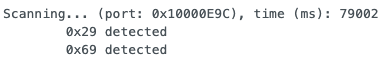
From the scan we can see the Tof device address as 0x29 (0b 0010 1001). Since the least significant bit is used to indicate read/write, it is soley a matter of shifting the 7-bit 0x29 address left by one bit to make space for the read/write bit that appears in the data sheet. Thus, the scanned address matches the data sheet as it is just a shift left away from matching the 0x52 8-bit address.
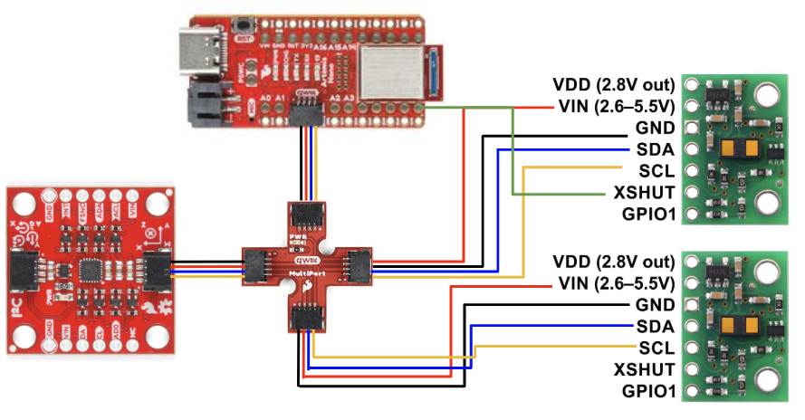
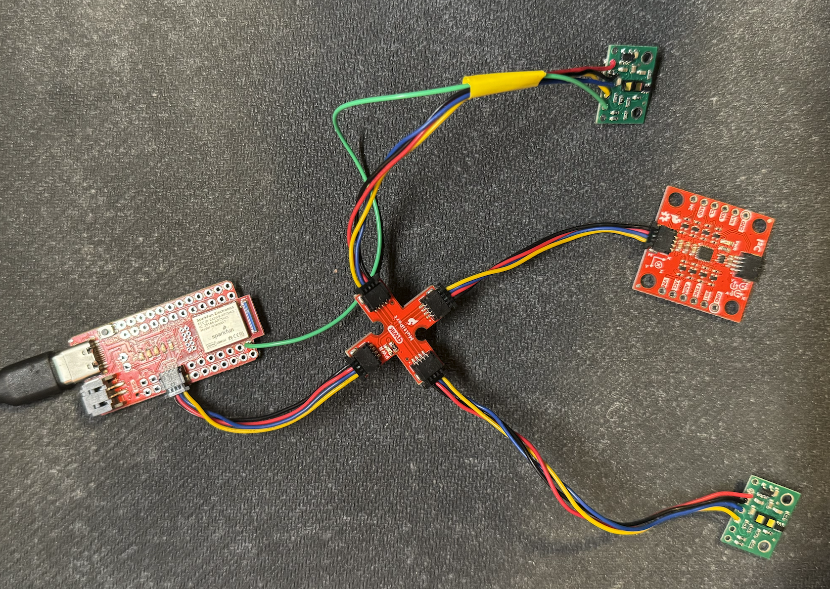
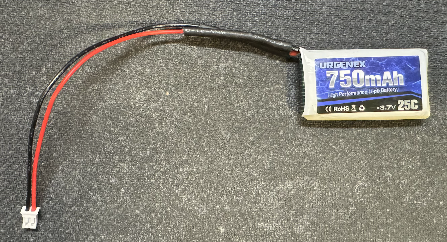
Physical Connection
In the below images you can see the battery leads soldered to the QWICC connect cables and the ToF sensors wired as outlined in the schematic:
Two ToF Sensors In Parallel Test
From the following video we can see the two ToF sensors working in parallel. I noticed that when the clearance for my ToF sensor drops below 20 mm, they tend to output 0 mm. However, this is to be expected since according to section 3.3 of the sensor data sheet, the minimum ranging distance is 4 cm. Overall, the sensors are accurate outside of this range.
I decided to use the long ToF mode distanceSensor1.setDistanceModeLong(). According to the data sheet: “long distance mode allows the longest possible ranging distance of 4 m to be reached.” In a classroom environment I believe that this longer distance will prove more useful for mapping even though it is at the cost of higher resolution at shorter distances.
ToF Sensor Speed
I tested the speed of my ToF sensors in two ways. The first was by printing the Artemis clock to the Serial as fast as possible and printing new ToF sensor data from both sensors only when available. The second was by testing the speed when called over bluetooth and compare it to the IMU.
- I used the following function to visualize and quantify the gap between each ToF data collection:
void
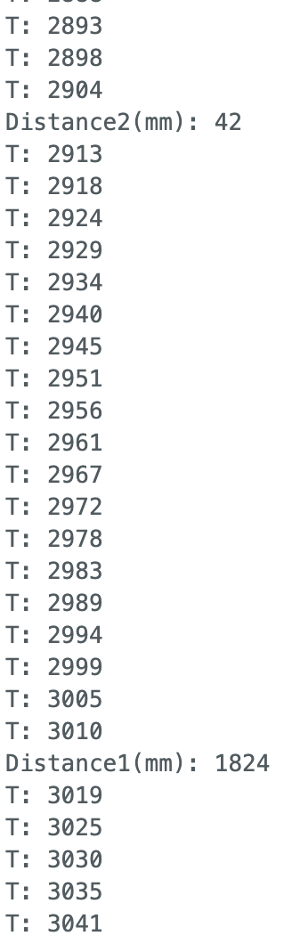
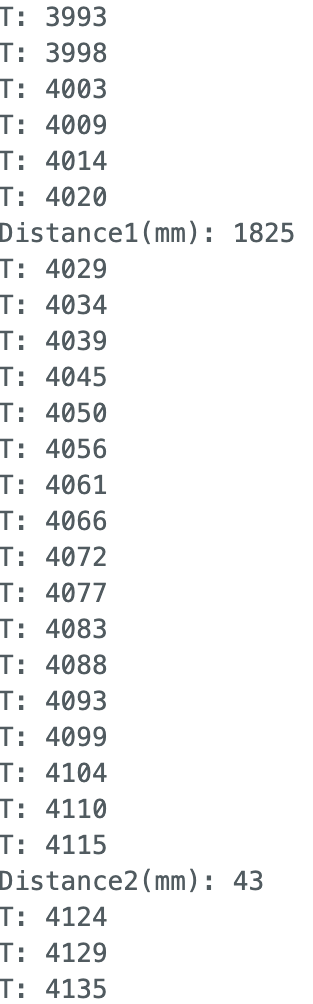
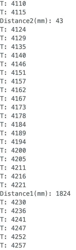
From the above three images you can see that the average gap between ToF sensor collection is 90 ms, corresponding to a rate of 11 Hz. Both sensor 1 and sensor two print at roughly the same rate.
- I created a function
collectTOF()to collect my ToF data in order to ensure the code doesn’t hang while it waits for the sensor to finish a measurement. It is called from the main loop when one of the two ToF sensors are ready AND mystartflag is true. The function populates a time and two ToF arrays with data. The data is parsed through via caseGET_TOF_READINGSto be sent over bluetooth.
void
After collecting data for 5 seconds (using my START_DATA_COLLECTION and STOP_DATA_COLLECTION command flags) the following number data points were collected from the IMU (function shown in Lab 2) and ToF sensors relative to the number of cycles through my main loop. This method helps eliminate the delay from print statments in the first speed test:
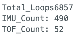
From the counters we can see that the ToF sensors were considerably slower than the IMU at recieving data and thus would be the limiting factor. After 5 seconds of data collection this corresponds 10 Hz for the ToF and 98 Hz for the IMU.
ToF Sensor Data (Over Bluetooth)
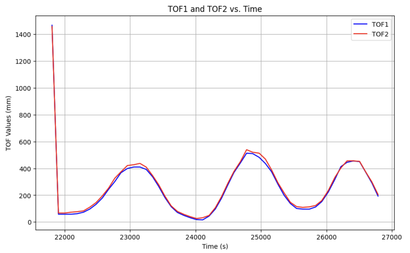
Here I created a Time vs. Distance graph of ToF data collected on the Artemis then sent over bluetooth:
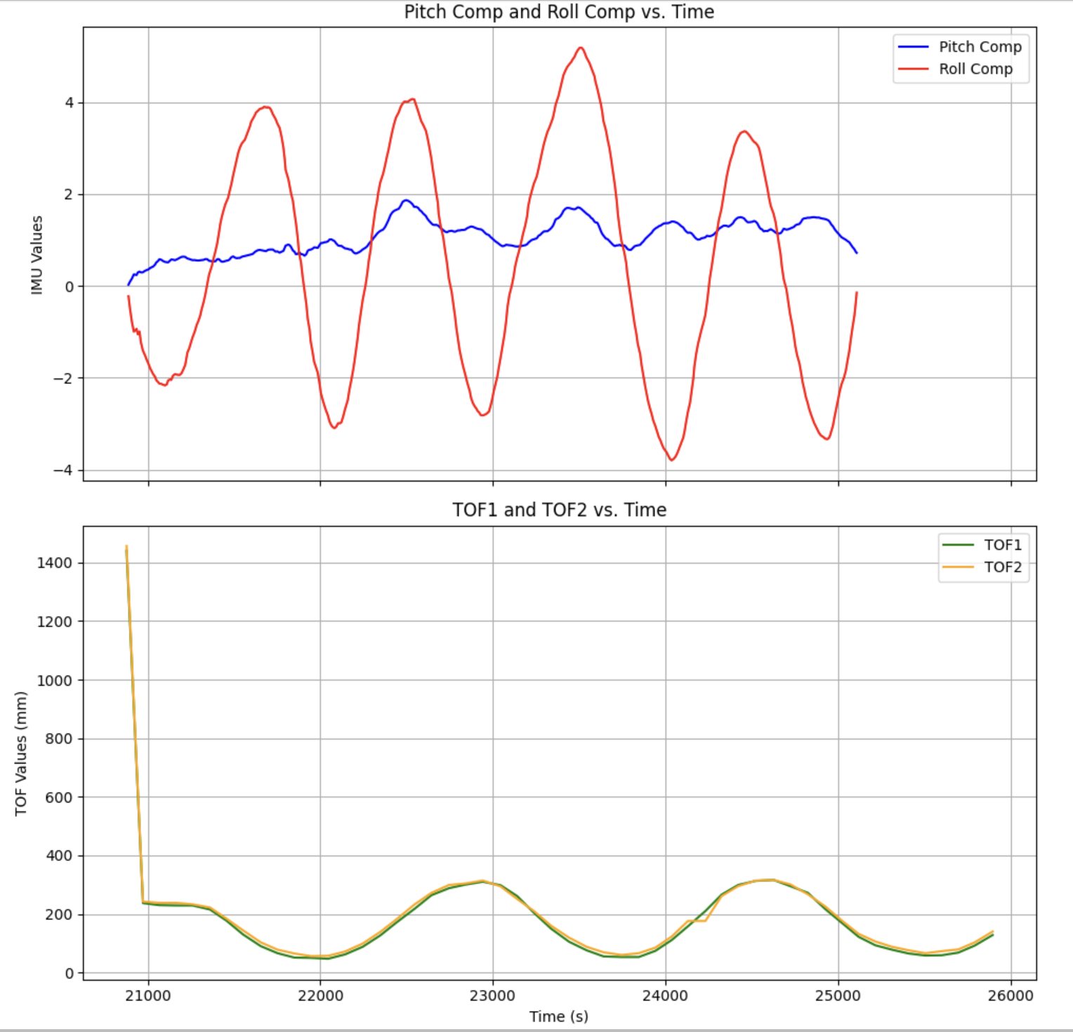
Here is another graph where I simultaniously collected ToF and IMU data for 5 seconds over bluetooth and graphed them on the same time axis. The complementary filter from Lab 2 was used for the IMU data:
ToF Accuracy
To quantify the accuracy of the ToF sensors I collected 10 seconds of data at three distances and graphed the data vs. time as well as the set target distance:
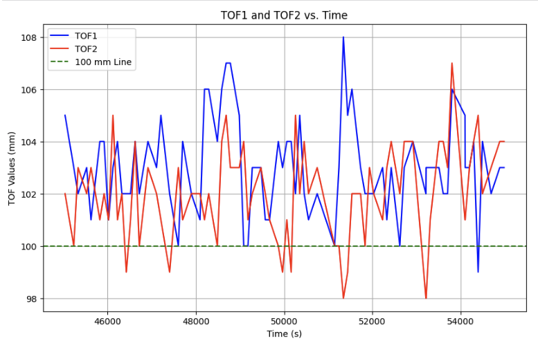
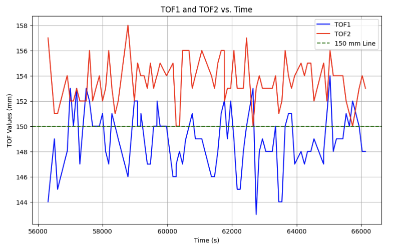
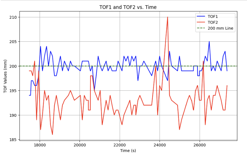
All around from the graphs you can see that the time of flight sensors are fairly accurate at a range of distances. While the testing setup was fairly precise, a few milimeters of variance is likely due to the human error in trying to perfectly align the placement of the sensors along my ruler. Nonetheless there is certainly some higher frequency noise in the ToF sensors which could likely be reduced by a LPF.
Collaboration
I collaborated extensively on this project with Jack Long and Trevor Dales. I referenced Wenyi’s site for my wiring setup, ToF sensor initiation, and sketch used to print out distance sensors in my serial monitor to test speed. ChatGPT was used to help plot CSV data and format graphs.